Edit the marker from the Attributes palette (see Marker Attributes). To add a shoulder to the leader line, click the Selection tool from the Basic palette and drag the control points on the object. The properties can be edited from the Object Info palette. Set the default properties, and click OK. The first time you use the tool in a file, a properties dialog box opens. To learn more about what a datum structure is or to request a quote for any of our services, send us a message through our Moeller Aerospace website.A datum feature symbol consists of a marker, leader, and datum reference letter.Ĭlick the Datum Feature Symbol tool from the Dims/Notes tool set.Ĭlick to place the object in the drawing, and click again to set the rotation. These are cast datum points used by the OEM to fixture the part and machine the bolt holes, flanges, etc. You’ll notice small flats spread out across the component (if they’re not covered up by heat shields or other elements). When given the opportunity to be involved in the early stage of a development with our customers, we provide input to sway the datum structure in a direction that meets the intended design and is efficiently producible.Īn everyday life example: Next time you’re under the hood of your car, take a look at something that starts out as a casting with machined features, such as an aluminum intake manifold, an exhaust manifold, or oil filter housing. Moeller Engineering & Operation teams have gained excellent knowledge on cost-efficient datum structures to ensure fixtures are simple to load, clamp, and inspect.

If the part only gets one platform machined and the convex platform is not machined but instead used as two points of the primary datum, this results in less machining, less inspection, less wasted material, and therefore, less cost. An example of this would be if a first station root form must be an “upload” due to the fact that datum -X- is on the convex side of the airfoil and so is “first side” root form. Sometimes, these datum structures are less than ideal for Moeller. Just like the Moeller machine processes, the casting vendors also have certain producibility constraints.įor example, a datum point right where a casting gate is required will not work well for anyone. The Casting ProcessĪnother reason is the casting process itself. These airfoils are designed to operate within a particular window to ensure safety, optimal performance, and consistent product life. The cast datum structure on a blade, for example, will ultimately control the location and rotation of the airfoil relative to the finished root form and/or Z lock features. They are typically well thought-out and placed in their locations for a multitude of reasons. These points/surfaces are defined on the part prints.

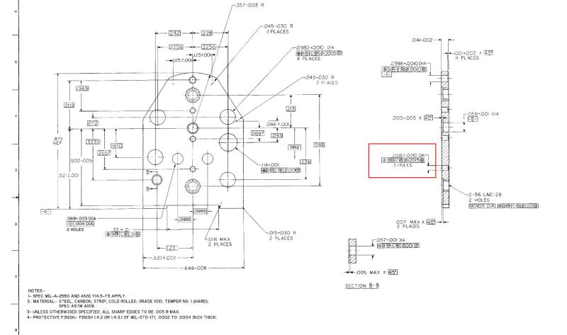
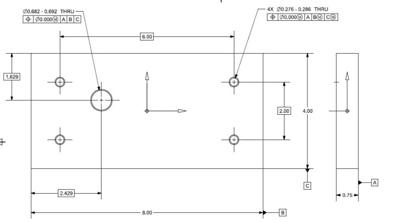
1 point constructs the tertiary datum (constrains in the third direction).2 points construct the secondary datum (constrain in a second direction and one rotation).3 points construct the primary datum (constrain in one direction and two rotations).This sets up what many refer to as a “cast datum nest”.Ī “nest” is a set of points or features that fully constrain a part: You may have seen drawings similar to that shown below. A datum structure is a combination of surfaces or points that set up the location and orientation of other geometry.


 0 kommentar(er)
